What is it?
The ESP8266 chip is a low-cost wifi enabled microcontroller that can be easily programmed using Python or the Arduino IDE. In this post I'll walk you through the process of getting a bare chip up and running. The following steps will help you setup a bare-bones option, but if you're looking for simple experimentation there are some pre-built boards that will handle all of the setup for you like the Adafruit Huzzah board.
Where to get the parts
I purchased this breakout board and the ESP8266-12E/F. I highly recommend the breakout board. The pin spacing on the ESP8266 does not match standard breadboard pin spacing making it difficult for prototyping.
Connecting the pieces
First you'll need to solder the chip to the breakout board. This is simple if you've had soldering experience. The one tip that I would give is to tape the chip down to the board as it has a tendency to slip. Once you've tacked a couple of the pins to the board you can remove the tape. 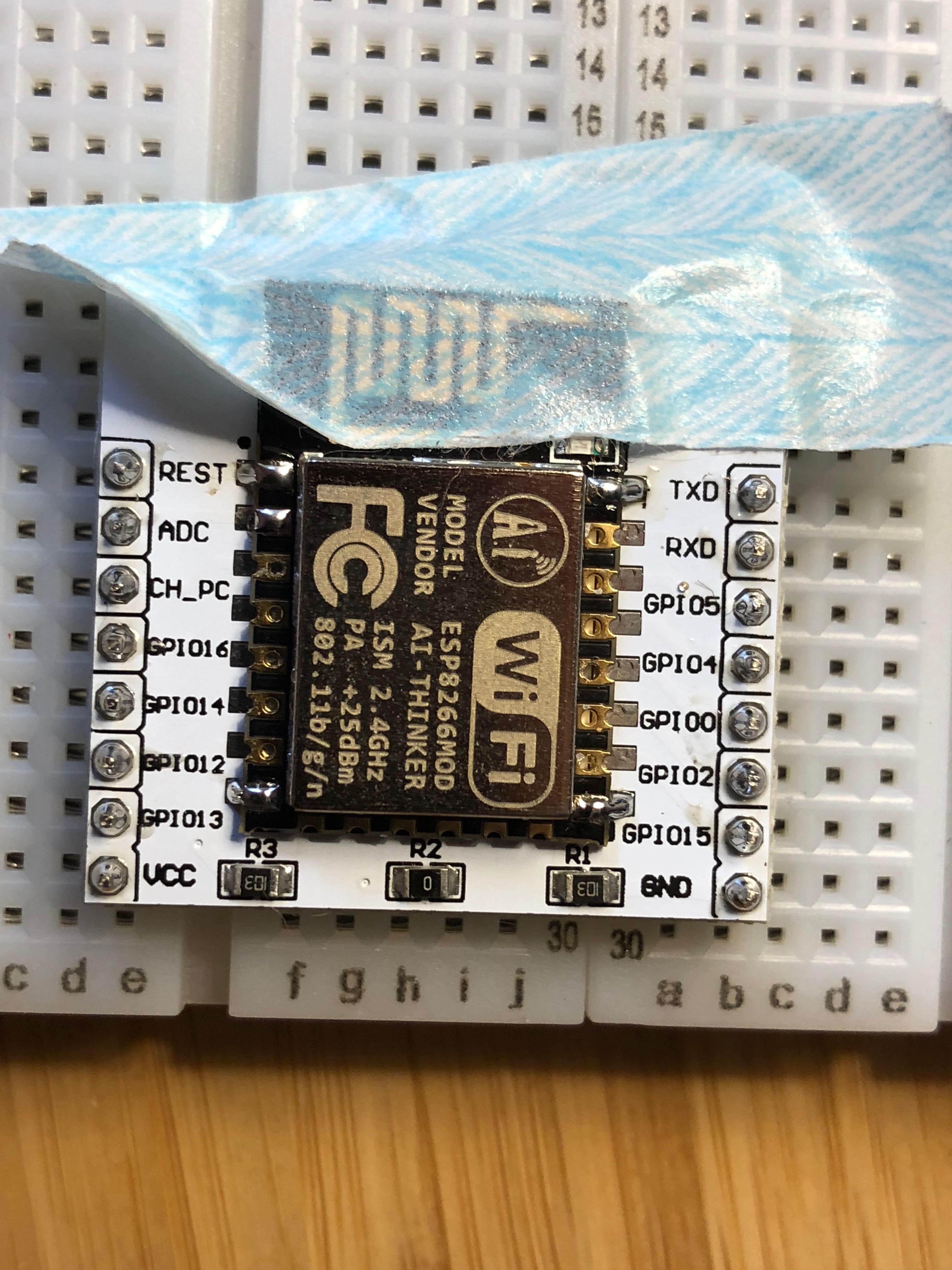
How to hook everything up for programming
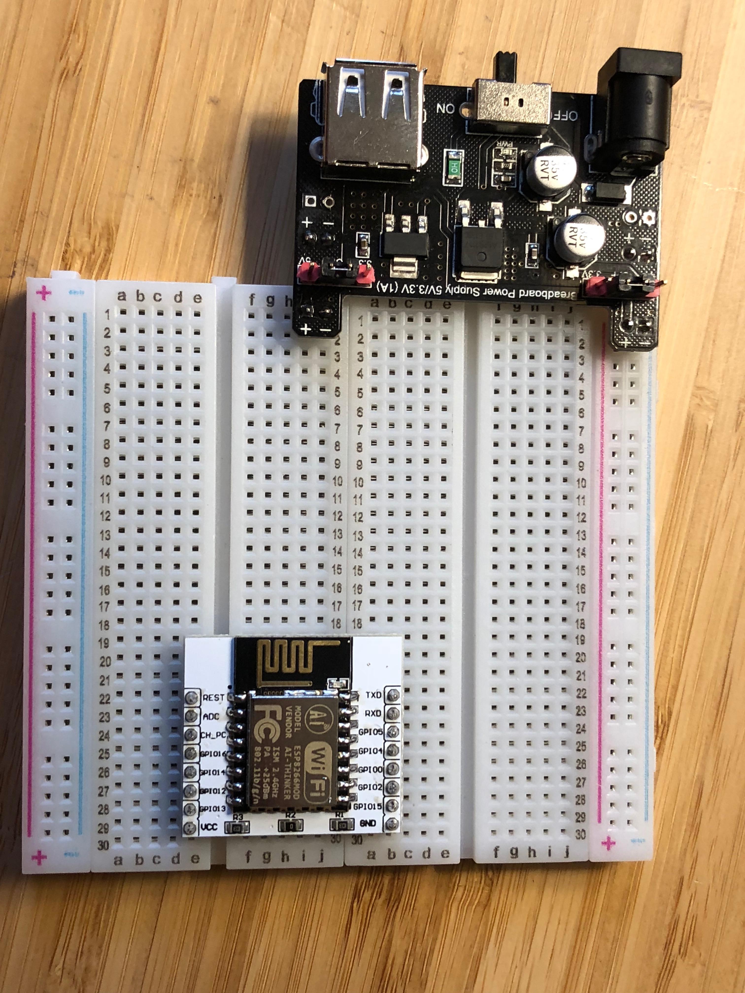
The first hurdle that I ran into is that the breakout board is exactly as wide as a standard breadboard, so it helps to have two that you can stack side-by-side to make room for additional wires. Once you've got that plugged in we can start making the appropriate connections.
1) Connect power!
I've hooked up a breadboard power supply to mine, but any 3.3v power supply will do. DO NOT USE 5v! It will fry the chip.
- Connect VCC to the + power rail.
- Connect GND to the - power rail.
2) Configure for flashing!
- Connect GPIO0 to GND (needed only when flashing)
- Connect CH_PC (sometimes labeled EN) to VCC (needed to 'enable' the board)
3) Connect the USB to FTDI chip
- Connect GND on the FTDI to the GND power rail.
- Connect RX on the FTDI to TX on the ESP8266
- Connect TX on the FTDI to RX on the ESP8266
Double check that you've got everything hooked up correctly, it can be a bit of a rat's nest for the initial flashing.
Now that we've got everything hooked up connect the FTDI to your computer and fire up the power!
Programming with Arduino
First you'll need to get the Arduino IDE configured appropriately. Sparkfun has a great tutorial written up about this here
Once you've gotten those steps completed you can start using the Arduino IDE to program the ESP8266.
I uploaded the "Blink" sketch to my board to test things out. On my board I had to set the led pin to pin 2 in order to get the blink code to work. It may vary depending on the board that you've purchased, but it is usually pin 1 or 2.
Remember that you'll need to connect GPIO0 to GND whenever flashing code to the board. Once the code is flashed it will automatically start running. If the power cycles and GPIO0 is still connected to GND then it will restart the chip in flash mode.
I've found that this board can be a little finicky. Generally if there are any issues they can be solved by a quick power cycle.
The Arduino IDE is a good programming environment, but for me the networking aspect was lacking. I wanted to experiment with something a little more powerful. For that I went through the process of flashing Micropython to the board.
Flashing Micropython
To flash Micropython you'll need to install the esptool.py tool. Instructions for installation can be found here.
Next you'll need to download the latest Micropython firmware.
Note: In the commands below I'll be using /dev/ttyUSB0 which is the serial port name for my computer. Your port name may differ depending on your OS and peripherals. Additionally the filename for the firmware may be different. Use the information below as an examples to get started.
Using esptool.py we'll now be able to flash the firmware. Make sure to use the same pin configuration as above and power on the ESP8266.
1) Use esptool to erase the flash on the board. This will make sure that we're starting with a clean slate..
python esptool.py --port /dev/ttyUSB0 --baud 115200 erase_flash
2) Upload the new firmware (It's a good idea to power cycle between steps)
python esptool.py --port /dev/ttyUSB0 --baud 115200 write_flash 0 esp8266-20180511-v1.9.4.bin
3) Verify the firmware and make sure it uploaded correctly
python esptool.py --port /dev/ttyUSB0 --baud 115200 verify_flash 0 esp8266-20180511-v1.9.4.bin
Using Micropython
Remove the GPIO0 pin connected to GND
Use putty on windows or screen on Linux to connect to the port at a baud rate of 115200. You should now have a Python REPL screen.
Run a simple loop to verify that things are working.
for i in range(100):
  print(i)
Using the REPL is a great way to test things, but if you want to write a script and have it work on a reboot you can use Ampy to load files to the ESP8266.
Now you should be all up and running and ready to go with your ESP8266 and Micropython!